


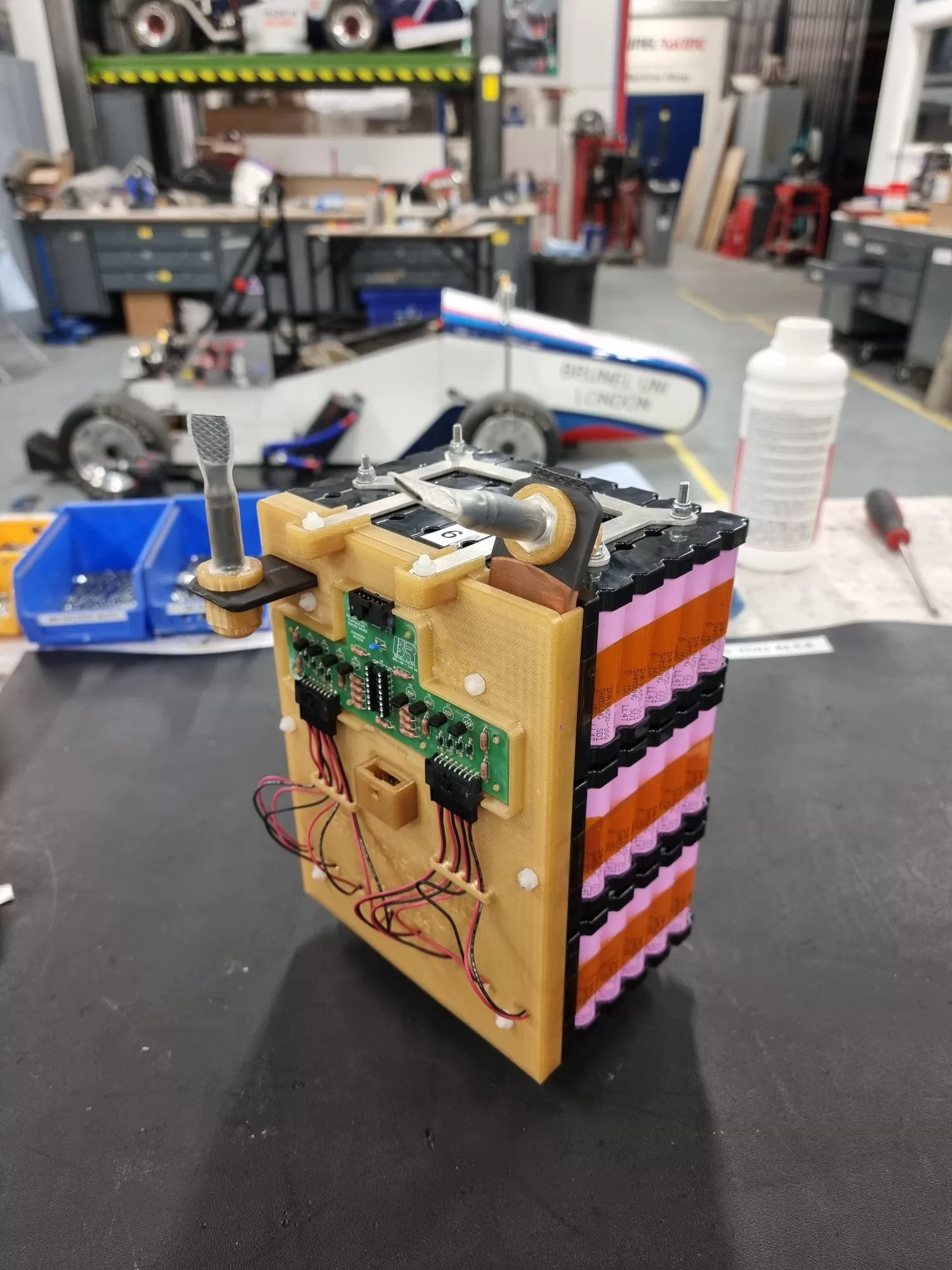
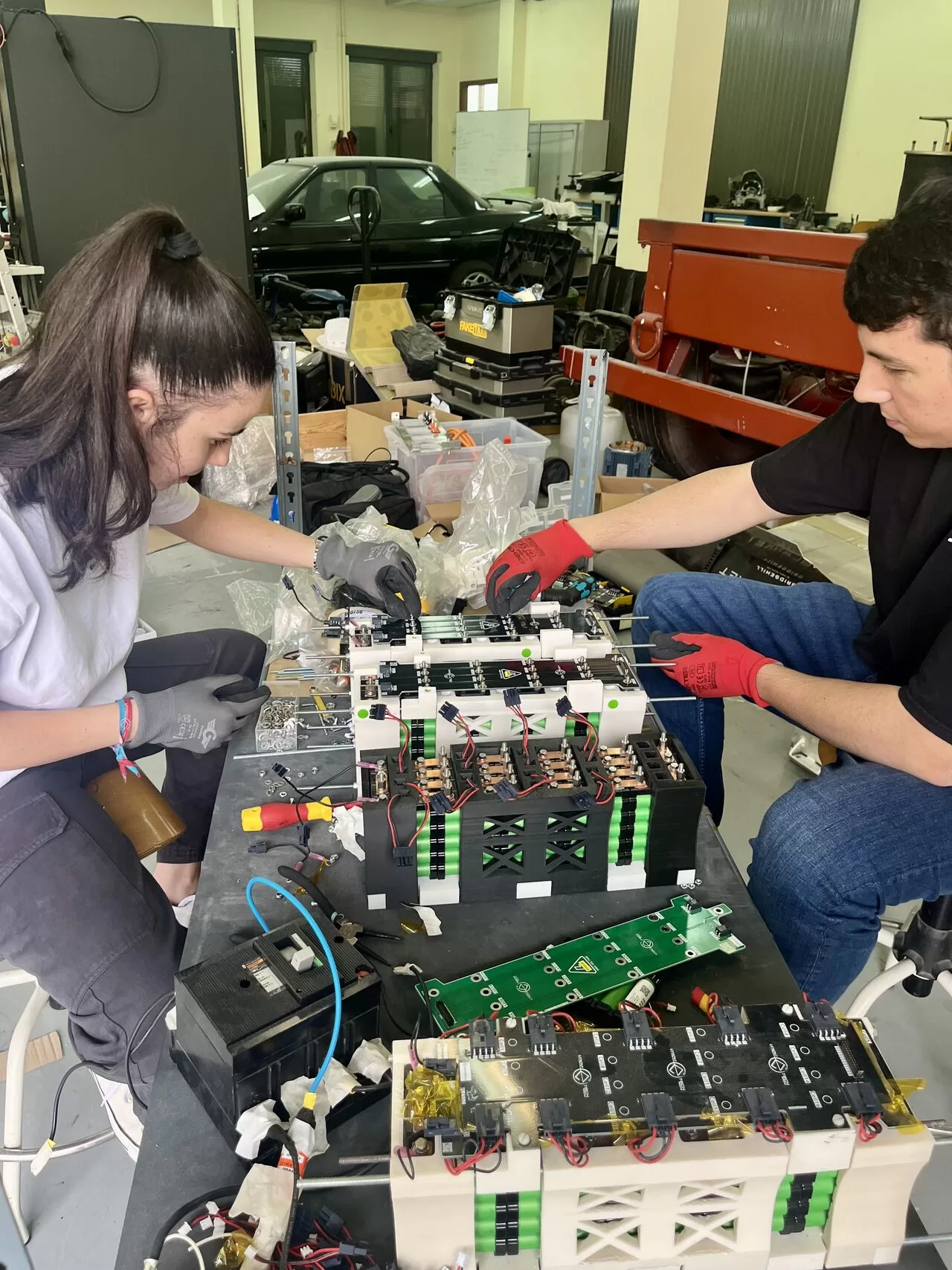
The “Brain” of the Battery
Advanced Battery Management
and Control Systems

Explore our advanced Battery Management and Control Systems, designed for Lithium batteries, including Li-ion, LiFePO4, Na-ion and supercapacitors.They optimize performance, ensure safety, and extend the lifespan of battery packs.
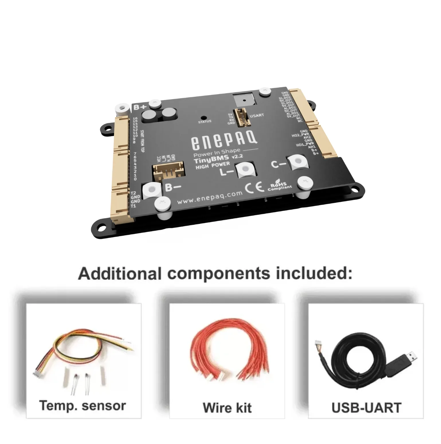
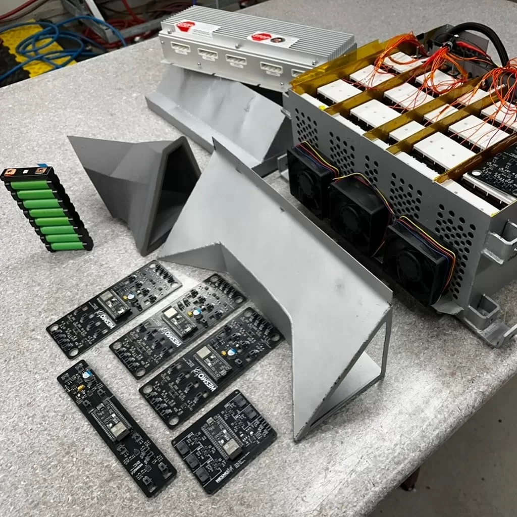
Battery Management System BMS – TinyBMS v2.2 High Power
Enepaq can tailor unique firmware and hardware BMS features to align with your unique project requirements.
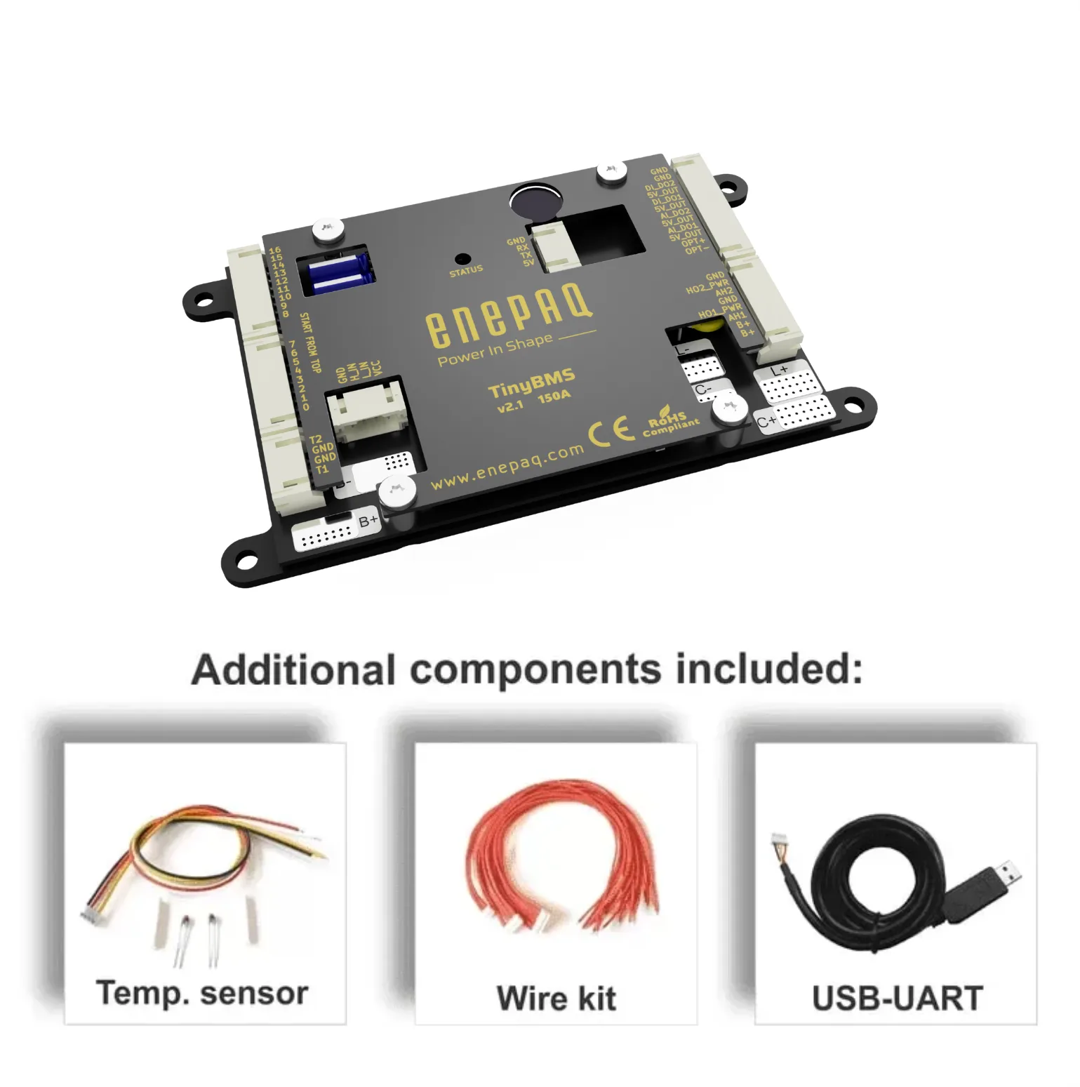
Battery Management System BMS – TinyBMS v2.1 High Power
Enepaq can tailor unique firmware and hardware BMS features to align with your unique project requirements.

Battery Monitoring System – TinyAFE up to 1000V
TinyAFE should be treated as an analog front-end for data acquisition and cell interface.
Efficient, Safe, and Scalable Energy Solutions
Our European-made battery management system reflects a strong commitment to innovation and quality. Our dedicated European-based team has crafted the Tiny BMS to ensure reliability and efficiency. This system shapes the future of sustainable energy solutions, supporting local economies and fostering a greener world.
The Tiny BMS is also CE Certified, guaranteeing compliance with the highest safety, health, and environmental protection standards in the European Union.
Application
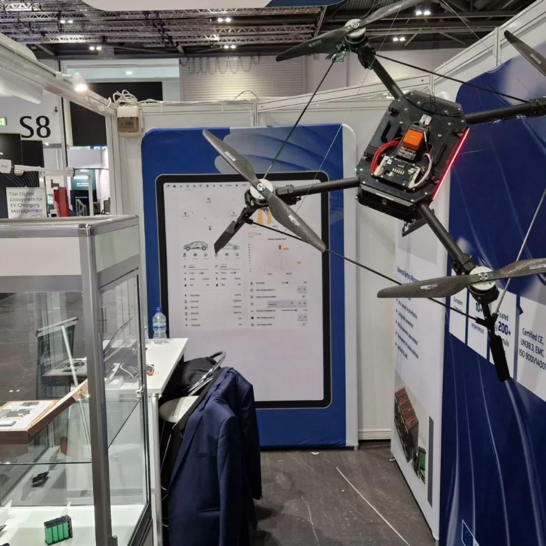
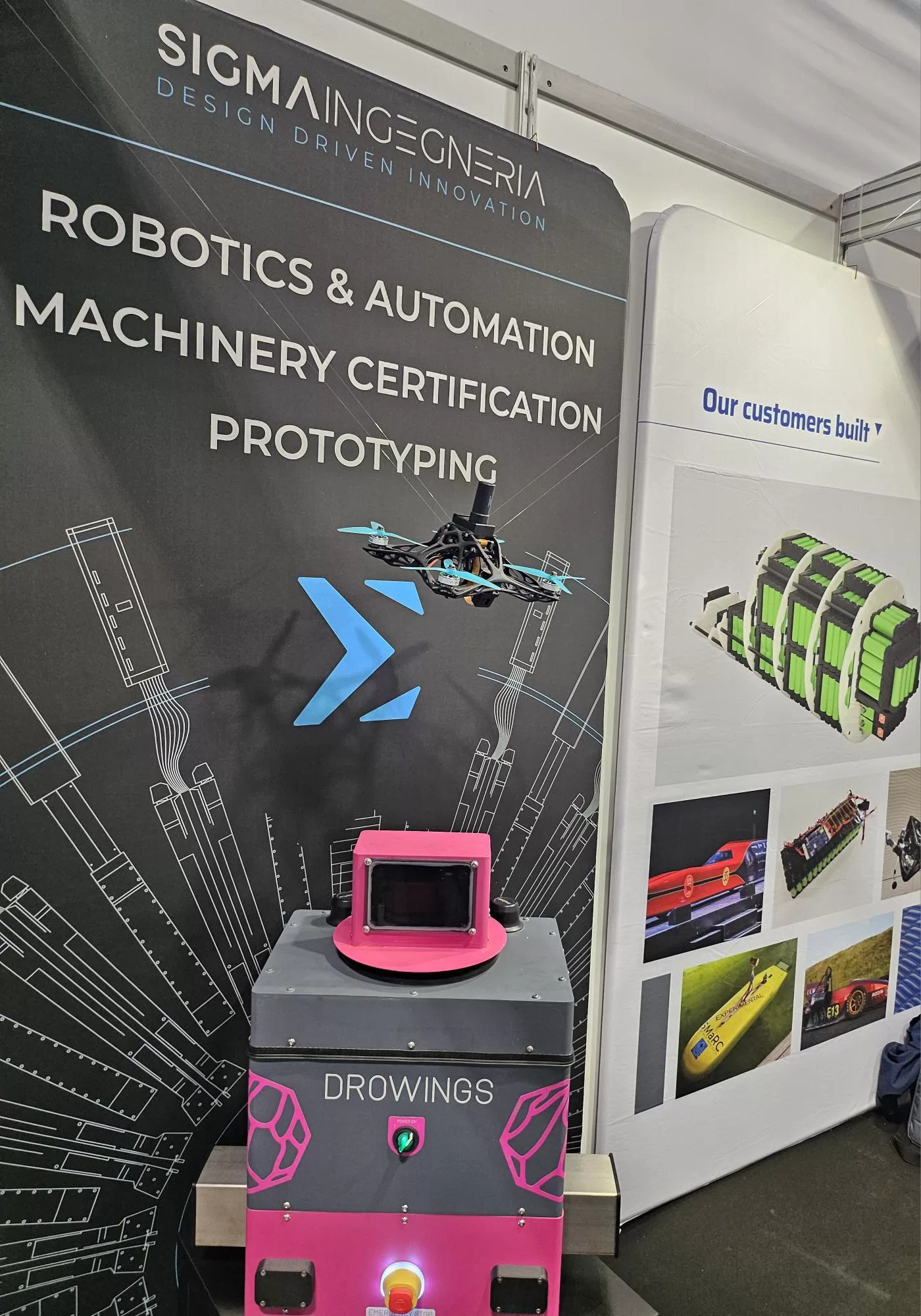
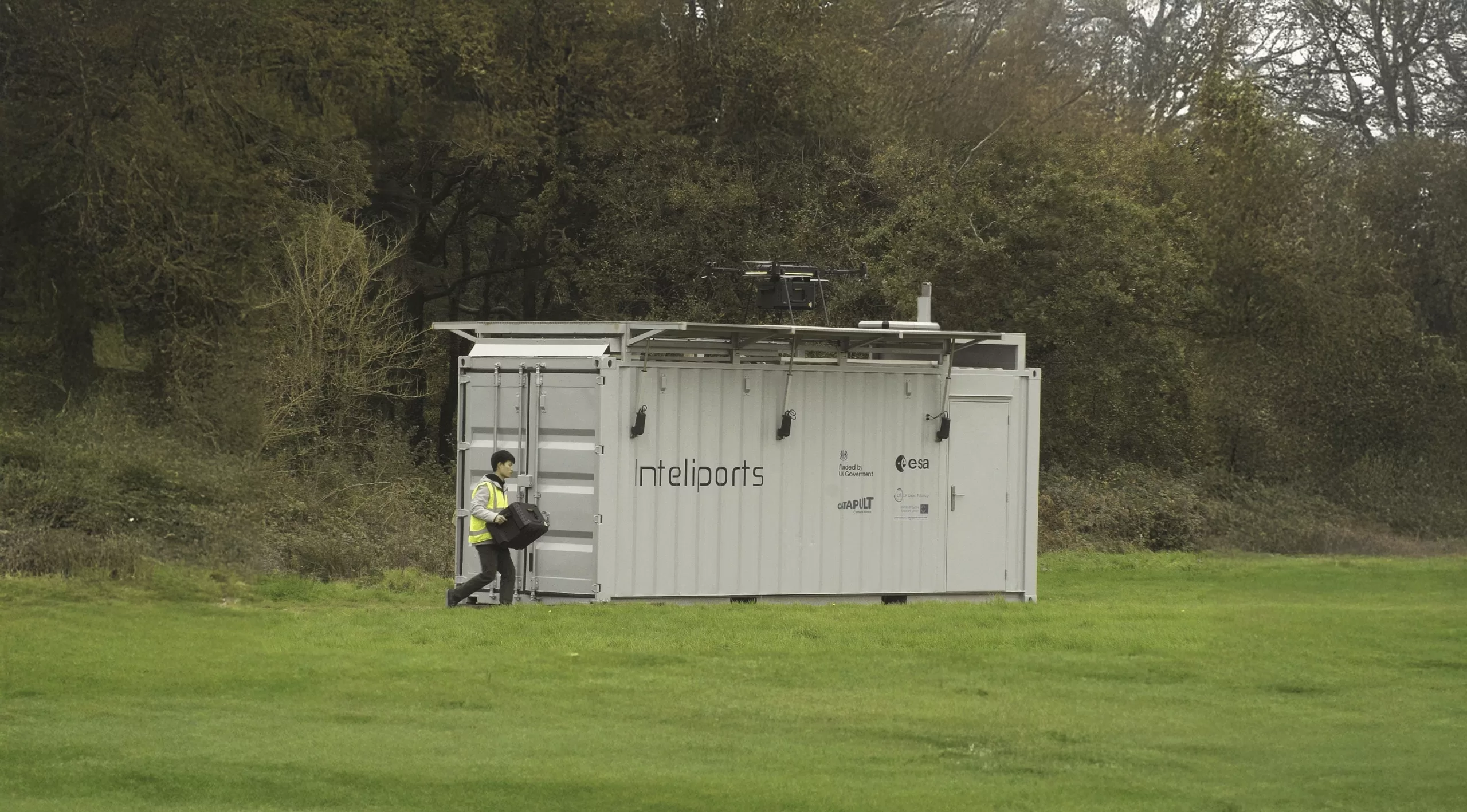
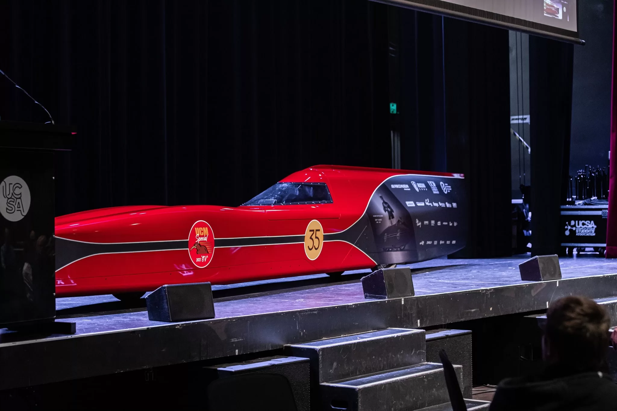
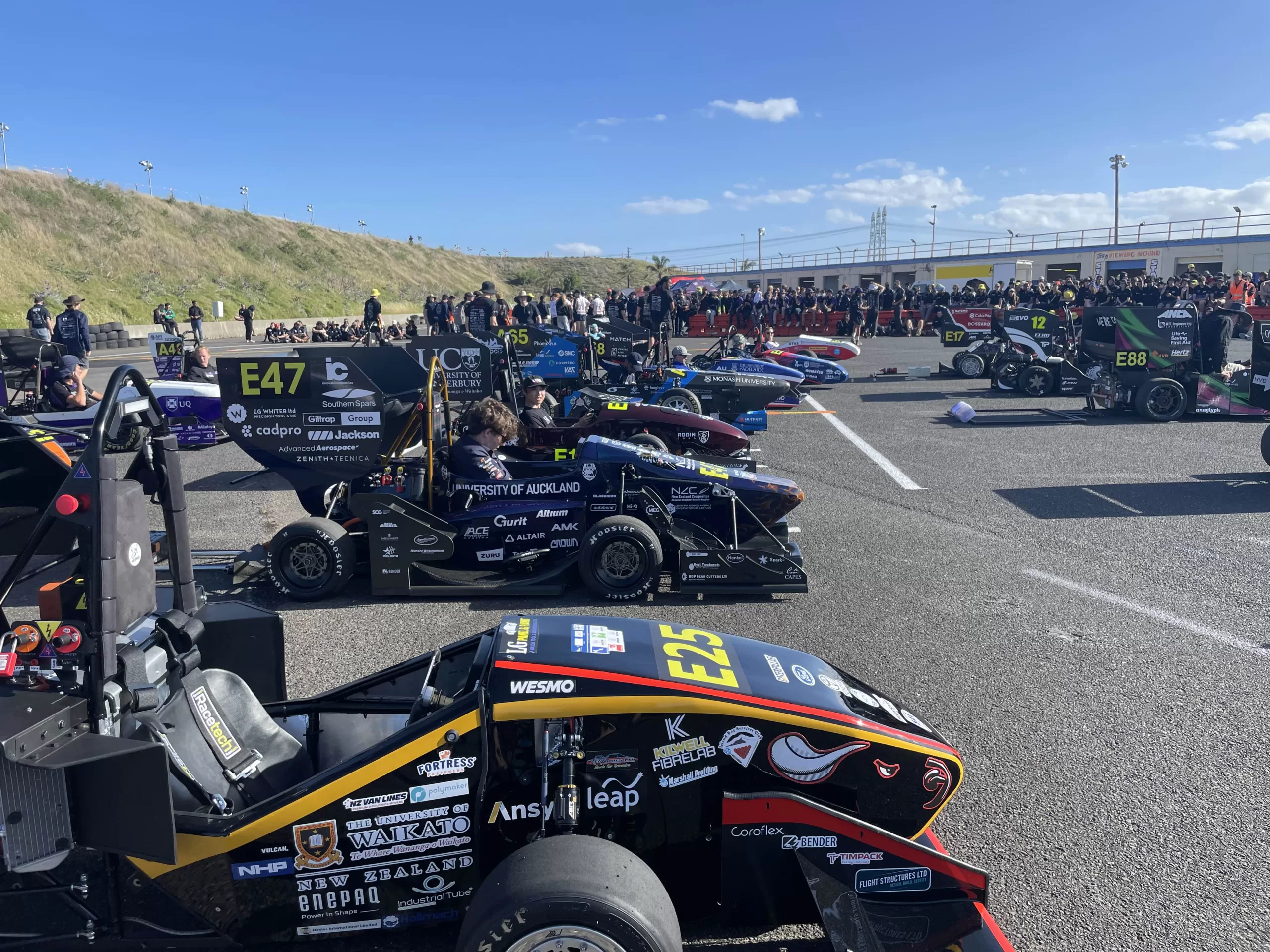
Powering Innovation Across Industries

Renewable Energy Storage
Our BMS plays a crucial role in seamlessly integrating renewable energy sources, such as solar and wind, into your power systems. By effectively managing the charging and discharging cycles, our BMS ensures the optimal utilization of renewable energy, allowing you to maximize the efficiency of your renewable power generation.


Learn More About
Our Products

Let’s Build Your Perfect Battery Solution
Unsure which system suits your project? Our experts are ready to guide you in finding for best solution.
Explore Our Range of Innovative Products
Discover customizable and advanced products designed for every engineering challenge.